Wireless sockets or termination pins allow construction of fixtures with shorter signal path lengths compared to conventional wired designs. The shorter path length allows for improved signal integrity from the tester circuits to the unit under test (UUT). Fixtures built in this manner are referred to as “wireless”and they improve impedance characteristics, allow greater bandwidths for analog test signals and higher vector rates for digital testing.
A wireless socket or termination pin has a non-replaceable interface probe as its termination. This interface probe typically contacts a dedicated PCB/interface/translator board on the fixture. The bottom probe is noncycling and it is designed to last the life of the socket. Replace the wireless assembly if the socket is damaged or worn.

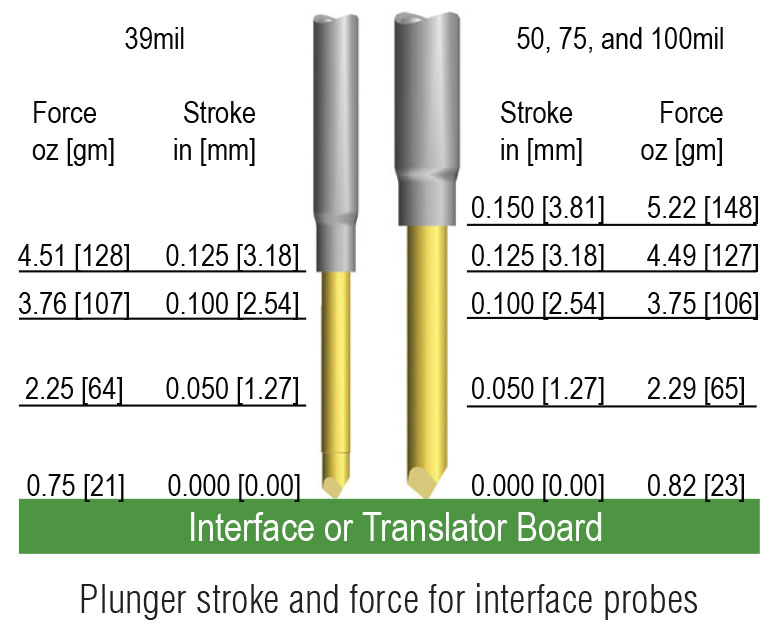
The top of the socket or termination pin accepts standard probes from the appropriately sized series and is replaceable, as routine maintenance requires. When mix mounting QA’s 39mil wireless sockets with 50mil, 75mil, and 100mil wireless sockets, the fixture designer must consider that the full plunger stroke of the 39mil wireless socket is only 0.125 [3.18] stroke versus the 0.150 [3.81] stroke for the others.
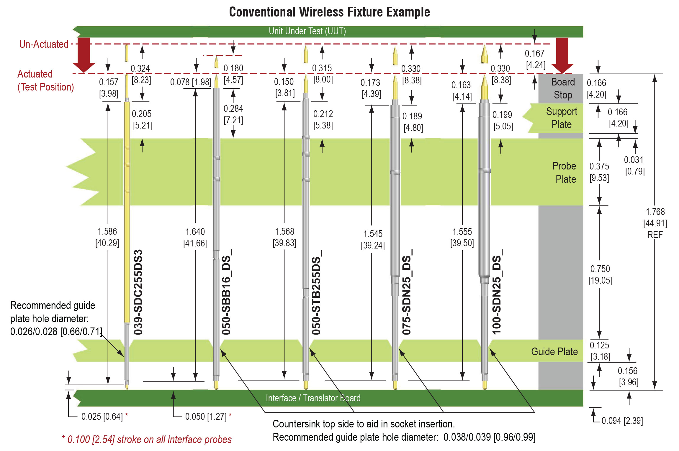
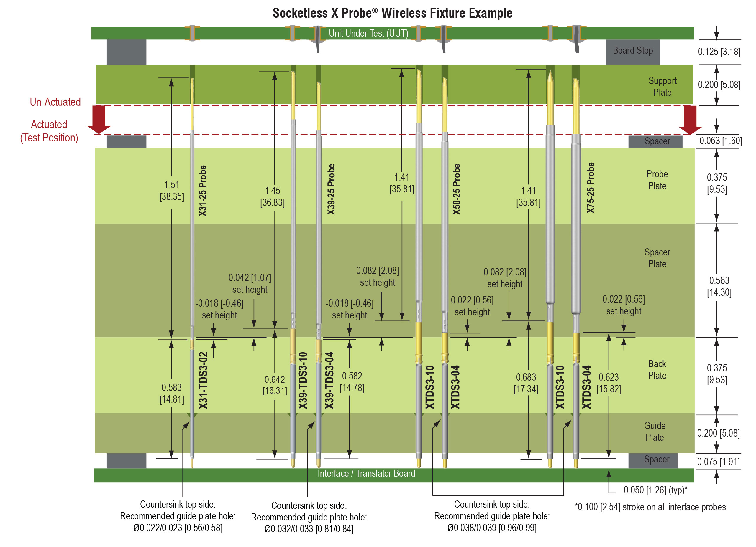
Ultimately, the set height and board layout are dependent upon the specific fixture design and application. QA recommends a guide plate to help maintain alignment between the interface probe and the contacts on the dedicated PCB/interface/ translator board. Here’s a suggested layout as a reference.


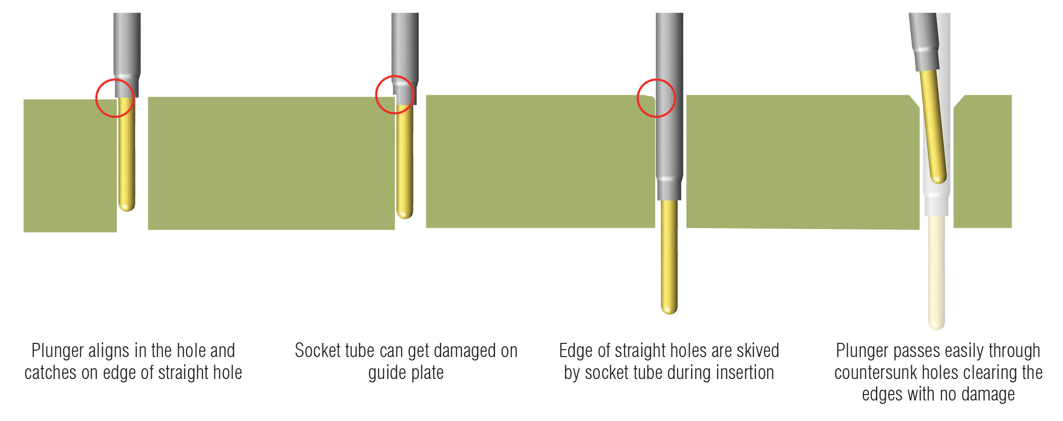
The illustrations below show the advantages of using a countersunk guide hole on the top of the guide plate.
