There are many wiring options to connect your fixture. QA Technology offers several different methods to ensure that you make a reliable connection for successful testing. These include wire wrapping, soldering, and crimping, as well as wire grip sleeves, wire plugs, and wire jacks for smaller sizes.
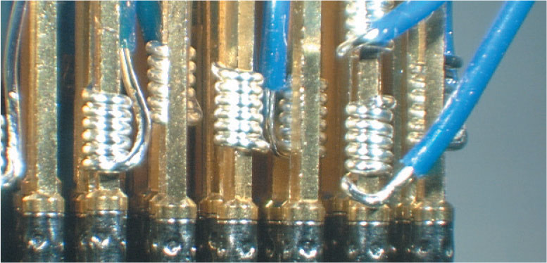
Wire wrapping is the most common wiring method for QA sockets and termination pins. For 75mil and larger centers, use 28AWG solid wire. For 50mil and smaller centers, use 30AWG solid wire to prevent crowding between adjacent sockets. Modified wraps are not recommended on 50mil centers. On all wire wrap pins longer than 0.250 [6.35], multiple wire wraps can be used.
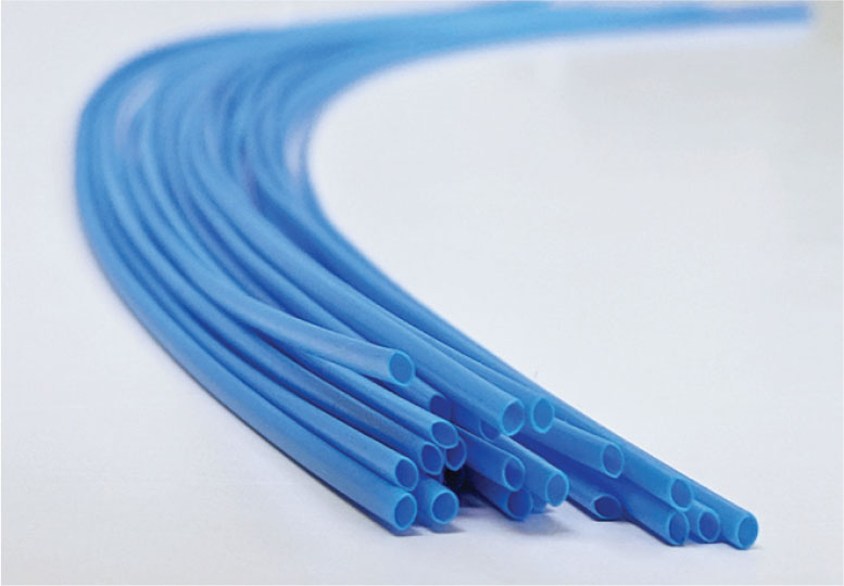
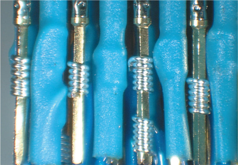
For 50mil centers or smaller QA recommends insulating every other connection to prevent adjacent sockets from shorting. Our heat-shrinkable tubing (INS046-6) is stiffer than other types making installation easier. It is colored to help identify progress during the wrapping process.
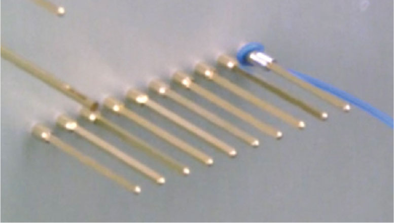

Cut and strip one end of the wire. A minimum strip length of 0.625 [16] will achieve the recommended six to seven regular wire wrap turns. For 50mil centers or smaller see further insulating instructions.
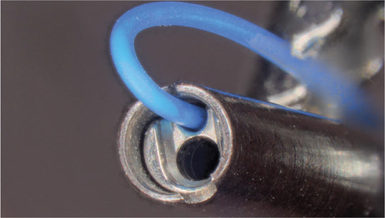
Insert the wire into the smaller of the two holes until the wire insulation contacts the face of the tool as shown.
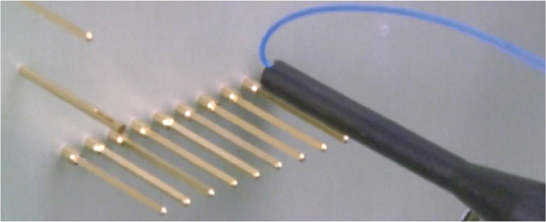
Align the larger center hole with the pin and slide the tool down to the desired wrap location. The nose of the tool will determine the starting point of the wrap.
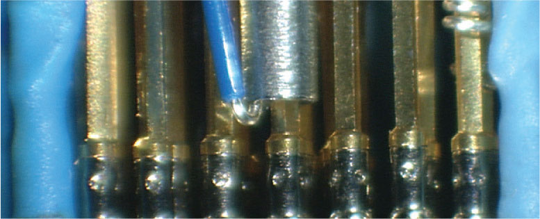
Holding the insulated end of the wire firmly, apply gentle pressure downward and pull the wrapping tool trigger. Do not pull the tool backwards or push with excessive force. Keep the tool on the pin until the wrap is completed.
Cut lengths of 0.500 [13] will completely cover the wire wrap post in most applications.
Slide the tubing on every other wire BEFORE wrapping.
Wire wrap all pins.
Slide the tubing to cover the wire wrap.
Heat the tubing with a heat gun to make it shrink around the wire and hold it in place.
If shrink tubing is present, slit it lengthwise with a penknife and pull it off with needle-nose pliers, taking care to avoid damage to the surrounding wires.
Place the unwrapping tool on the post, use moderate forward pressure, and rotate it in a direction opposite to the wrap until the coil has loosened enough to be removed by hand.
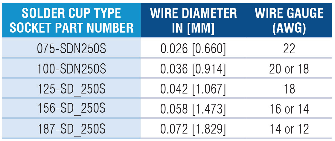
A solder connection is another common method to secure an electrical bond. QA offers a solder cup termination option for 75mil sockets and larger. QA suggests using lead-free solder. If choosing stranded wire, you may need the next smaller gauge. The accompanying chart indicates the solid wire sizes that are suggested for the various solder cup sockets we offer.
For 125, 156, and 187mil sizes, 12AWG and 10AWG wire can be used for high current testing. However, be sure that the wires are secured, as heavier wires can bend the sockets if not supported and adjacent sockets could touch or short.
Wire connections on small centers can be challenging. QA has wire grips, wire jacks, and wire plugs that are great wiring options. Refer to our catalog or website for connection style availability.
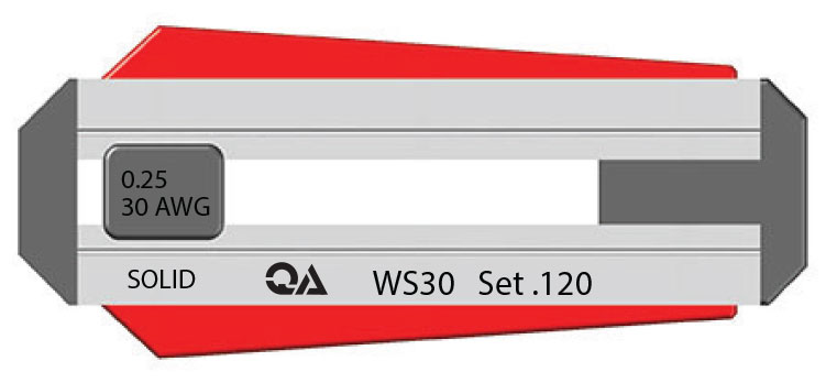
For wire grip, wire plug, or wire jack installation, use a solid Kynar insulated copper wire stripped to 0.120 [3.05] (multi-stranded wire is not recommended). QA offers wire strippers (WS) preset to this length and available in 28AWG or 30AWG sizes for this purpose.
Wire grip sleeve connection is used with our “G” type termination socket or termination pin.
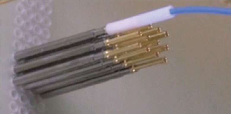

Slide the sleeve onto stripped wire.

Lay the wire and sleeve into the channel of the wire grip installation tool (GTR) and slide it until the sleeve bottoms on the inner shoulder of the tool.
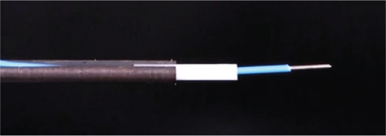
While holding the wire firmly, push the wire until the insulation bottoms on the “G” type termination. The stripped wire will be exposed through the slot of the termination.
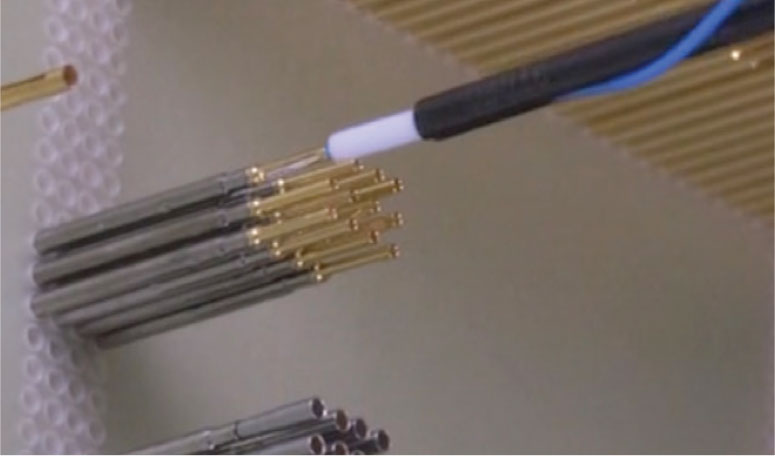
Continue sliding the sleeve until the stripped wire stops on the shoulder of the socket or termination pin and the exposed wire is completely encased.
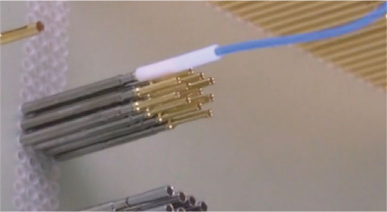
Use needle-nose pliers to slide the sleeve off the wire, pulling straight back while wiggling the wire back and forth until the wire is freed. Remove any broken pieces to prevent possible shorting in the fixture.
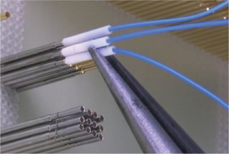
Wire plugs connect into any “P” type termination sockets.
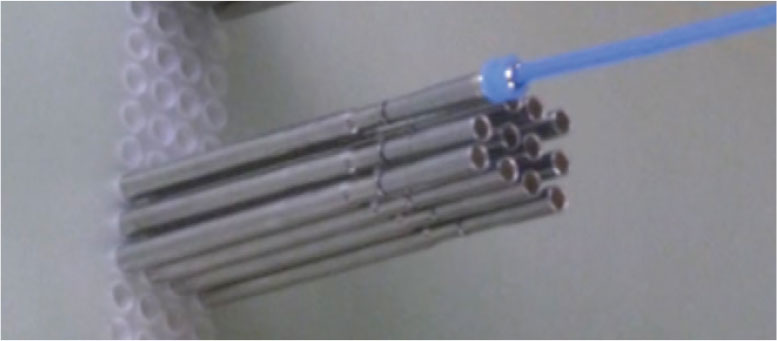

Insert the wire into the wire plug until the insulation stops against the internal shoulder and bare wire protrudes through the end of the wire plug.
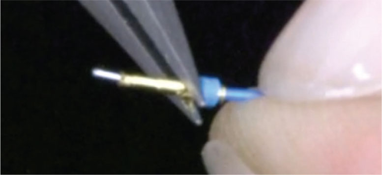
Lay the wire into the channel of the wire plug installation tool (WTR) and slide it until the wire plug sits at the tip of the tool.
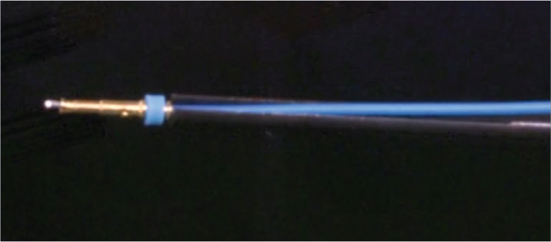
Push the wire plug assembly into the back of the “P” type socket. You will feel a positive “click” when the assembly is complete.
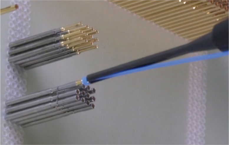
Wire plugs are reusable and may be removed by pulling straight back on the wire plug as shown. The wire plug will remain attached to the wire.
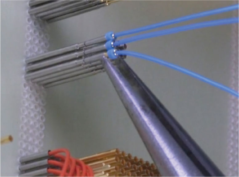
The wire jacks accepts 28AWG or 30AWG wire sizes and is available with or without pre-crimped wire. Wire jacks connect to “J” type sockets and termination pins.
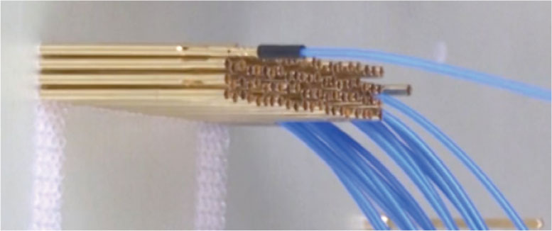

Place the wire jack assembly into the wire jack installation tool (JTR) seat the wire jack insulator into the tip of the tool.

Push the wire jack assembly into the back of the “J” type socket or termination pin. You will feel a positive “click” when the assembly is complete.
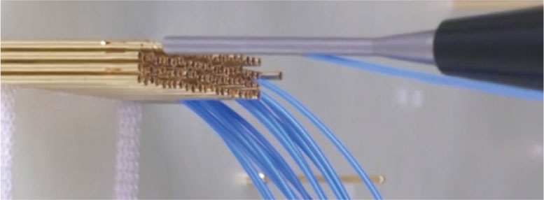
Wire jacks are reusable and can be removed by pulling the wire jack straight back. The wire jack will remain attached to the wire.
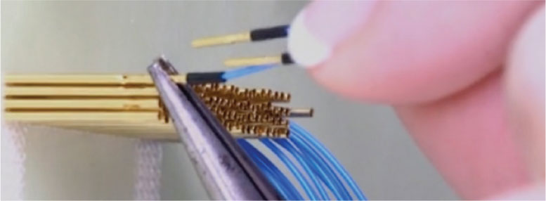
More details can be found in our Wire Connection Methods video