Ensuring that you install termination pins and QA Technology X Probes® correctly provides the best pointing accuracy, retention force, and overall performance. Be sure to select the appropriately sized tool for the product you are using.
Termination pins are installed in the back plate of a fixture and are used to adjust the set height of the probe. They provide the electrical connection from the probe to the fixture wiring.
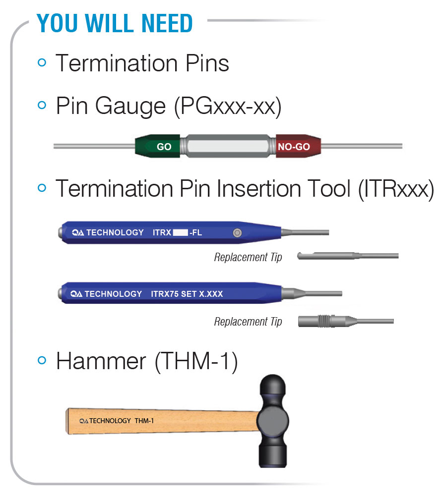
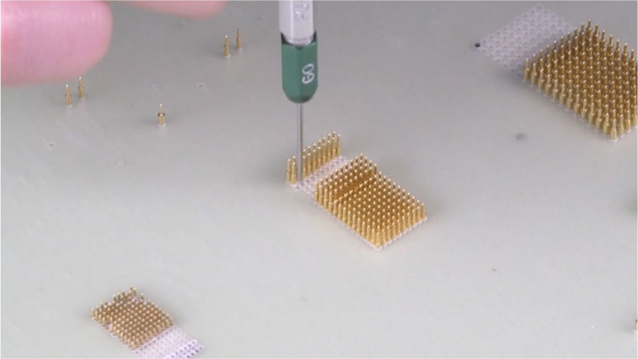
Check that the mounting hole is sized correctly with the proper pin gauge (PG) tool. The RED side should not enter the hole, while the GREEN side confirms the hole size is correct and ready for the termination pin.
When drilling laminates such as AT7000 and G10/FR4, there is usually a difference between the drill diameter and the actual measured diameter of the finished hole. Drill feed, spindle speed, and material affect choice of the proper diameter drill. QA Technology recommends solid carbide, printed circuit board drills with 1/8” shanks.
Insert the termination pin into the correctly gauged mounting hole, tail end first. The bottom retention bead should sit on top of the back plate. When termination pins have a pre-attached wire, thread the wire through the mounting hole and gently pull on the wire until the first retention bead contacts the back plate. Do not try to pull the retention beads through the plate by the attached wire as the wire could pull apart from the body of the termination pin.
Place the nose of the termination pin installation (ITRX) tool over the interconnect pin and tap lightly with a small hammer (THM-1) until the nose of the tool contacts the mounting plate. Because of the delicate nature of the ITRX31 and ITRX39 tools, take extra care so as not to damage the tool.
Inaccurate hole sizes and excessive hammering can cause damage to the termination pins or fixture plates.

Sheared off retention beads leave metal shavings that could cause electrical shorts.

Mounting plate material may be displaced due to excessive hammering.

Damage to the shoulder of the termination pin and inconsistent set heights can occur with excessive hammering.
It is important to use our probe installation (PT) tool to prevent damage to the sharpest of tip styles. Do not use a metal pusher because it can damage the tip and plating on the plunger.
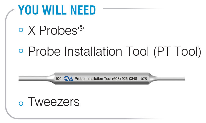
After the probe and optional spacer plates are installed, install the probe into the hole onto the termination pin by hand or with tweezers, avoiding the mouth area the probe tube.
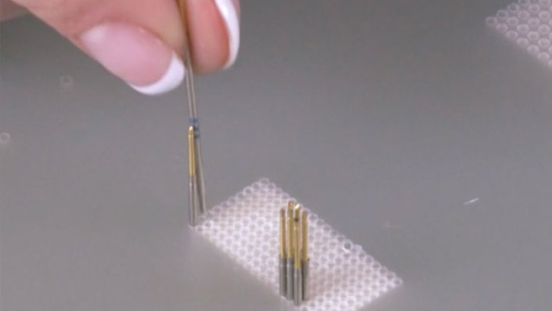
Using the probe installation (PT) tool, push on the probe tip guiding it onto the termination pin. Continue pushing until you feel a positive click.
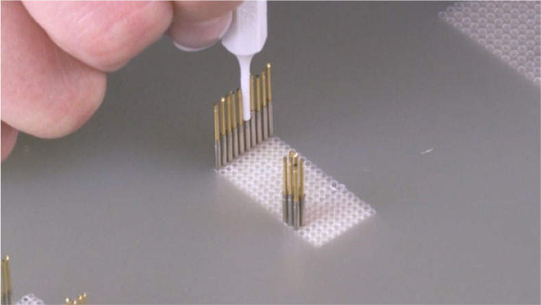
Properly sized holes and installation is key. The following are some things to check if poor electrical contact or shorts are experienced:

Proper X Probe installation, bottom of probe tube is sitting on shoulder of Termination pin.

The X Probe may have missed the termination pin and is not making the connection. Remove the X Probe and re-install.

If the X Probe is sitting too high, it may not be seated properly. Continue pushing down until the connection is complete.
To replace a worn or damaged probe, the following methods can be used
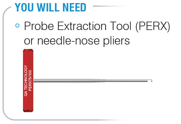
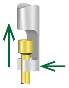
For headed probes, slide the hook of the probe extraction tool (PERX) under the head and pull straight up to remove the probe. For headless probes, use needle-nose pliers.
You can also remove a broken probe by using one of the following optional methods. Always remove the remaining components, such as the plunger or spring, with needlenose pliers to begin.
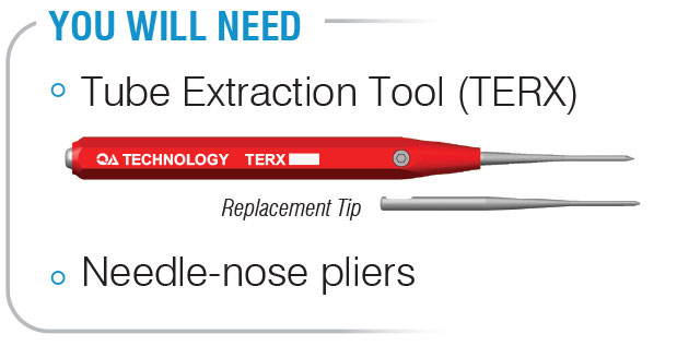
Insert the tube extraction tool (TERX) into the damaged probe tube. If the tube has become deformed, you can also use this tool to reform the tube. Push firmly into the probe tube, taking care not to push so hard that the termination pin will move.
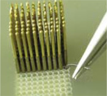
Pull the broken tube out.
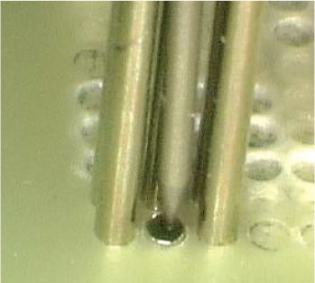
Insert a plunger, point end first, or insert a buss wire into the damaged probe.
Solder the plunger or buss wire into the broken off probe tube. Be careful not to solder the probe tube into the mounting hole. In some cases where the tube does not allow you to install a plunger, use a pointed awl to reform the tube. Pull the damaged tube from the socket with needle-nose pliers.
Pull the damaged tube from the mounting hole with needle-nose pliers.
Using a small pin vise and the proper size drill bit*, insert the drill bit straight down into the broken probe tube and twist it.
* Drill Bit Sizes:
039/X31 = Method #3 is not recommended as standard drill bits are not readily available
050/X39 = #70 Drill bit (.0280) [0.71]
075/X50 = #66 Drill bit (.0330) [0.84]
100/X75 = #57 Drill bit (.0430) [1.09]
After a few rotations with the pin vise and drill bit, pull straight up. The drill bit will grab the ID of the damaged tube so that you can pull it straight from its mounting hole.
Damaged termination pins can be removed with or without the probe and optional spacer plates installed.
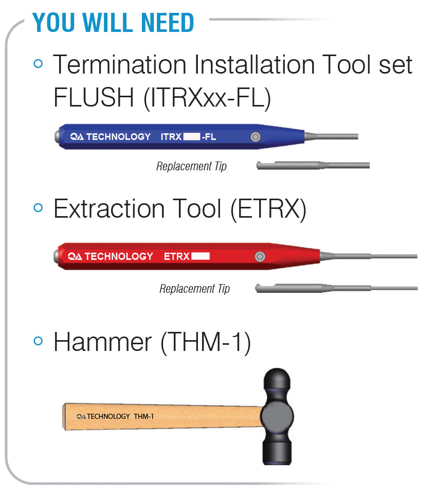
With the Probe and Spacer Plates Removed:
Following these instructions will ensure that the back plate will not be damaged when replacing a termination pin.
We recommend the termination pin first be set to 0.000 or flush with an insertion (ITRX-FL) tool prior to extraction. (For termination pins set below 0.000, this step is not required).
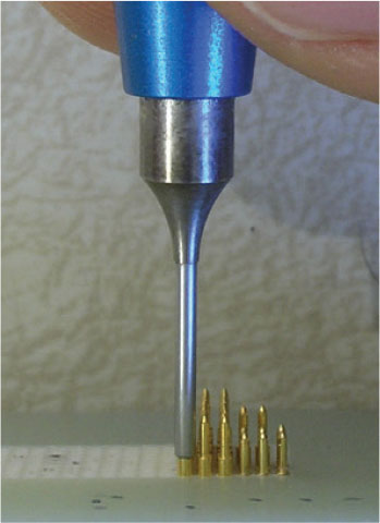
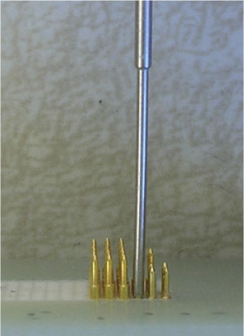
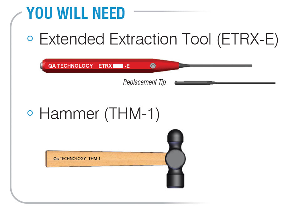
Place the nose of extraction (ETRX) tool onto the termination’s interconnect pin and lightly tap with a small hammer (THM-1) until it’s driven out. With care, the tool will also remove the termination pins with broken interconnect pins.
With the Probe and Spacer Plates Instaled:
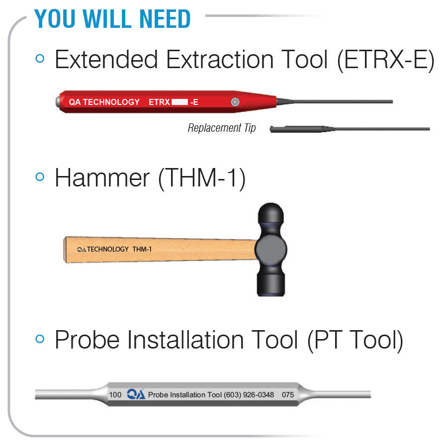
At times, it is not practical to remove all of the probes and disassemble the fixture in the field. Use our extended extraction (ETRX-E) tools to remove and re-install terminations pins in fixtures where the probe and spacer plates are installed.
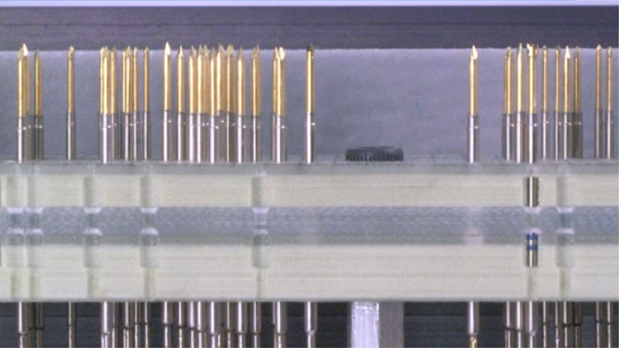
Remove the X Probe from the probe plate (see instructions above).
To help prevent damage to nearby contacts during extraction, identify the termination pin from the bottom side of the back plate and move adjacent wires and components.
Guide the nose of the extended extraction (ETRX-E) tool into the mounting hole in the probe plate until the nose of the tool contacts the termination’s interconnect pin.
With a pencil or fine line marker, make a small mark on the shank of the tool located at the top of the probe plate. When installing the replacement termination pin, this mark is used to gauge the set height.
Lightly tap on the extraction tool with a small hammer (THM-1) until the termination pin is driven out.
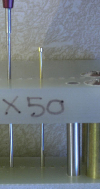
Proper use of extraction tool with spacer & probe plates installed.
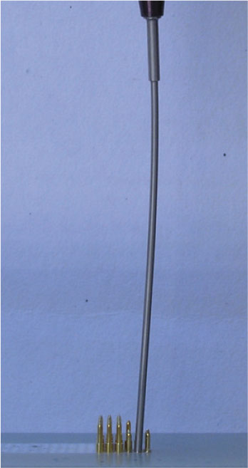
Incorrect use of tool.
ETRX-E tool may buckle.
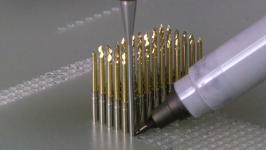
Re-installing the Termination Pin with the Probe and Spacer Plates Installed:
Check the mounting hole to make sure nothing is obstructing it. The extraction (ETRX-E) tool can be inserted into the hole to check this.
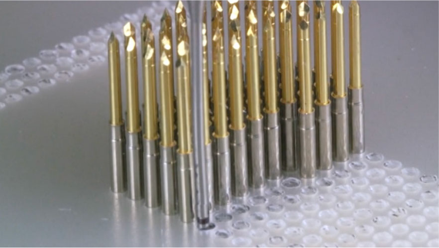
Drop the replacement termination pin into the hole, tail first. If the termination pin hangs up in the hole, use the extraction (ETRX-E) tool to push it to its starting position on the top of the back plate.
Lightly tap with a small hammer (THM-1) only to the point where the mark (made previously) on the tool shank aligns with the top of the probe plate. This ensures that it is set at the same height as the previously removed termination pin.
Reinstall the proper X Probe with appropriate probe installation (PT) tool or other plastic pusher.
Reconnect fixture wiring to the termination pin.
If termination pins require more than a light tap of the hammer to seat on the back plate, verify the hole size and make modifications if required.
Replacement termination pins can be installed from the bottom side of the back plate without removing the probes or probe and optional spacer plates. A custom tool would have to be fabricated by the user to support the termination pin during installation and provide positioning to be set at the proper set height. On high-density fixtures, the congested wiring on the bottom side of the back plate could make this method particularly challenging.
The tools are designed to remove and install termination pins in back plates up to 0.625 [15.88] in thickness when the fixture is designed around QA’s Fixture Layout Examples.
The wireless XTDS termination pins are used with both the X50 and X75 Probes. In cases where an X75 Probe is connected with an XTDS termination, the ETRX50-E tool would be used, not the ETRX75A-E tool.
Because of the delicate nature of the X31 and X39 tools, take extra care to avoid bending or damage.
Instructional video on how to install and remove X Probes and termination & pins. See Chapter 1 for termination pin installation.